Physics:Drift chamber
A multiwire chamber in which spatial resolution is achieved by measuring the time electrons need to reach the anode wire, measured from the moment that the ionizing particle traversed the detector. This results in higher resolution and wider wire spacing than can be obtained with simple planar or cylindrical multiwire proportional chambers. Fewer channels have to be equipped with electronics, although the cost per channel is increased. Drift chambers use longer drift distances, hence are slower than multiwire chambers; therefore, they are typically not used in the primary beam, in high-rate colliders, or for triggering purposes.
Drift chambers have been built in many different forms and sizes, and they are standard tracking detectors in more or less all experiments; this is true even in high-rate colliders, where the collision rate can be shorter than the maximum drift time. Planar (or cylindrical) chambers, with the drift in the same plane as the wires, have been operated with anode wires up to 50 cm apart, but more typically distances of some 5 cm are used. Non-planar chambers, with the drift direction orthogonal to the wire plane, exist in large varieties; the most ambitious developments are large jet chambers and time projection chambers. Shortest drift times are achieved in drift tubes. Recent developments are silicon drift chambers and microstrip gas chambers.
To translate good time resolution into spatial resolution, it is important to have a predictable electron drift velocity in the gas, and a simple relation for tracks passing under different angles; this means that the shape and constancy of the electric field needs more careful adjustment and control than in ordinary multiwire proportional chambers. In planar drift chambers, the anode wires are alternated with thick field-shaping cathode wires often called field wires , that reinforce the electric field right in between two anode wires. The anode wire is maintained at a positive potential, and the two field wires at the potential of the adjacent cathode wires. By choosing the proper voltages, a uniform drift field can be produced over the entire cell, for modest gaps in the order of 6 or 8 cm, and with anode wires in the order of 5 cm apart ( ![]() Field Shaping). Planar drift chambers measure the coordinates of the intersection of a particle track with a wire plane, by making the electrons drift in the plane. Hence multiple planes are needed to determine a trajectory; they are typically given several different wire orientations, to get different projections, thus offering the possibility of reconstruction in three dimensions.
Field Shaping). Planar drift chambers measure the coordinates of the intersection of a particle track with a wire plane, by making the electrons drift in the plane. Hence multiple planes are needed to determine a trajectory; they are typically given several different wire orientations, to get different projections, thus offering the possibility of reconstruction in three dimensions.
Drift tubes , stand-alone cylindrical detectors with a single sense wire along the axis, are used in various arrangements (but typically in large numbers) when short drift time is needed, as in hadron colliders ( ![]() Drift Tube);
Drift Tube);
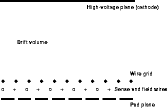
Jet chambers made of multiple independent cells, with a single wire plane in a moderate drift volume, often using drift on both sides of the wire; the left-right ambiguity is resolved by staggering the wires (displacing alternate wires in the drift direction, by a small amount), so that ghost (wrongly assigned) digitizings will not result in a smooth track. The drift direction in a jet chamber is roughly perpendicular to the wire plane, with only a small amplification region. Thus a single trajectory gives rise to many hits on different wires. Given multihit electronics, two-track resolution can be very good (hence the name jet chamber); ionization sampling is also possible. The effect of a magnetic field (Lorentz angle) has to be taken into account, e.g. by tuning the potential on the cathode wires. Precision along the drift is typically 100 [math]\displaystyle{ \mu }[/math]m, and can be better than 50 [math]\displaystyle{ \mu }[/math]m with pressurized gas (jet chambers are also in use close to the vertex). Two-track resolution is 1-3 mm, and precision by charge division along the wire is a few centimetres. Fully explained examples can be found in Blum93.
Time projection chambers or TPCs for short, share many of the properties of jet chambers; their drift volumes are larger (up to 200 cm), and the sense wires are arranged in one end face; the effect is that no left-right ambiguity can arise, and signals induced in pads or strips near the sense wire plane can be used to obtain three-dimensional information. Also, the drift direction being often along the magnetic field, diffusion is reduced. On the other hand, the long drift time and the difficulty of shaping the field are drawbacks: space charge builds up, and inhomogenities in the field can cause serious degradation of the precision. Introduction of ion-stopping grids (``gates), careful tuning of the drift field (sometimes by an additional ``potential wire plane), and gas purity are of paramount importance to the resolution achieved in these chambers.
The achieved precision along the drift direction is typically 150-200 [math]\displaystyle{ \mu }[/math]m, and the precision along the wire, by charge division, is a few centimetres.
For more details, ![]() Blum93 (with many examples), Lohse92, Aarnio91, and Peisert84, also in the proceedings of various specialized conferences, e.g. Krammer95 or Villa86. Basic considerations on precision can be found in Sadoulet82, on readout of wire chambers in Radeka91.
Blum93 (with many examples), Lohse92, Aarnio91, and Peisert84, also in the proceedings of various specialized conferences, e.g. Krammer95 or Villa86. Basic considerations on precision can be found in Sadoulet82, on readout of wire chambers in Radeka91.


